Seeed XIAO RA4M1をArduino IDEで開発
概要
勉強のためにSeeed XIAO RA4M1を購入したので覚書として確認した内容を記録しておきます。
Renesasマイコン搭載ということで簡易的な開発はArduino IDEで出来ますし、突っ込んだ開発をするときも個人的に使い慣れているARMのアーキテクチャなので助かります。
マイコンボードにリチウムイオンバッテリーの充放電回路が標準で搭載されているのも魅力的です。充放電回路をユニバーサル基板で組むのはなかなかに面倒なのでかなり助かります。この辺りを裏面パッドではなくピンで出してあるマイコンボードが出てくれると更に選択肢が広がるのですが。。。
参考サイト

実行環境
MCU: Seeed XIAO RA4M1
IDE: Arduino IDE 2.3.6
Seeed XIAO RP2040のピンアサイン
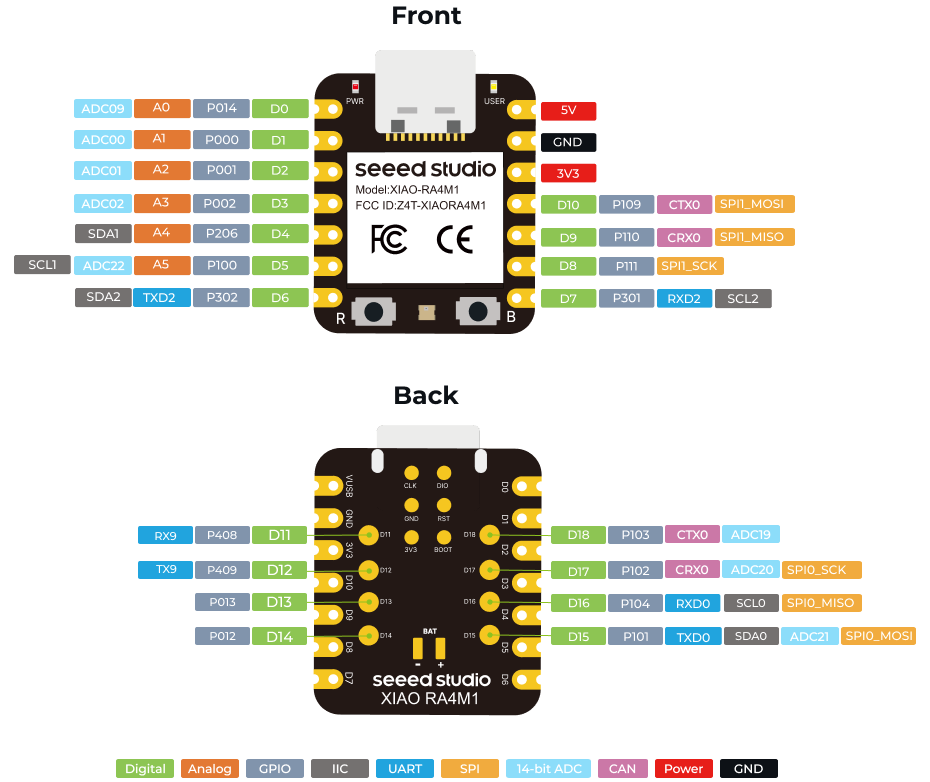
ボード固有の定義
以下はpins_arduino.hの抜粋です。
#define DAC         A0

static const uint8_t A0 = PIN_A0;
static const uint8_t A1 = PIN_A1;
static const uint8_t A2 = PIN_A2;
static const uint8_t A3 = PIN_A3;
static const uint8_t A5 = PIN_A5;

// Digital pins
// -----------
#define PIN_D0   (0u)
#define PIN_D1   (1u)
#define PIN_D2   (2u)
#define PIN_D3   (3u)
#define PIN_D4   (4u)
#define PIN_D5   (5u)
#define PIN_D6   (6u)
#define PIN_D7   (7u)
#define PIN_D8   (8u)
#define PIN_D9   (9u)
#define PIN_D10   (10u)
#define PIN_D11   (11u)
#define PIN_D12   (12u)
#define PIN_D13   (13u)
#define PIN_D14   (14u)
#define PIN_D15   (15u)
#define PIN_D16   (16u)
#define PIN_D17   (17u)
#define PIN_D18   (18u)

static const uint8_t D0 = PIN_D0;
static const uint8_t D1 = PIN_D1;
static const uint8_t D2 = PIN_D2;
static const uint8_t D3 = PIN_D3;
static const uint8_t D4 = PIN_D4;
static const uint8_t D5 = PIN_D5;
static const uint8_t D6 = PIN_D6;
static const uint8_t D7 = PIN_D7;
static const uint8_t D8 = PIN_D8;
static const uint8_t D9 = PIN_D9;
static const uint8_t D10 = PIN_D10;
static const uint8_t D11 = PIN_D11;
static const uint8_t D12 = PIN_D12;
static const uint8_t D13 = PIN_D13;
static const uint8_t D14 = PIN_D14;
static const uint8_t D15 = PIN_D15;
static const uint8_t D16 = PIN_D16;
static const uint8_t D17 = PIN_D17;
static const uint8_t D18 = PIN_D18;

#define digitalPinHasPWM(p) (IS_PIN_PWM(getPinCfgs(p, PIN_CFG_REQ_PWM)[0]))
// LEDs
// ----
#define PIN_LED     (19u)
#define LED_BUILTIN PIN_LED
#define PIN_RGB      (20u)
#define RGB_BUILTIN PIN_RGB
#define PIN_RGB_EN   (21u)

/****** RTC CORE DEFINES *******/
#define RTC_HOWMANY     1


/****** UART CORE DEFINES ******/

#define SERIAL_HOWMANY		2
#define UART1_TX_PIN        6
#define UART1_RX_PIN        7

#define UART2_TX_PIN        12
#define UART2_RX_PIN        11


/****** WIRE CORE DEFINES ******/

#define WIRE_HOWMANY      1
#define WIRE_SDA_PIN      4
#define WIRE_SCL_PIN      5

#define SOFTWIRE_SDA_PIN     14
#define SOFTWIRE_SCL_PIN     13

static const uint8_t SDA = WIRE_SDA_PIN;
static const uint8_t SCL = WIRE_SCL_PIN;

/****** SPI CORE DEFINES ******/

#define SPI_HOWMANY       2

#define PIN_SPI_MOSI    (10)
#define PIN_SPI_MISO    (9)
#define PIN_SPI_SCK     (8)
#define PIN_SPI_CS      (7)
#define FORCE_SPI_MODE  (MODE_SPI)

#define PIN_SPI1_MOSI   (15)
#define PIN_SPI1_MISO   (16)
#define PIN_SPI1_SCK    (17)
#define PIN_SPI1_CS     (18)
#define FORCE_SPI1_MODE (MODE_SPI)

static const uint8_t MOSI = PIN_SPI_MOSI;
static const uint8_t MISO = PIN_SPI_MISO;
static const uint8_t SCK  = PIN_SPI_SCK;
static const uint8_t CS  =  PIN_SPI_CS;
static const uint8_t SS  =  PIN_SPI_CS;

/****** GTP CORE DEFINES *******/

#define GTP32_HOWMANY     2
#define GTP16_HOWMANY     6
#define GPT_HOWMANY       8

/****** AGT CORE DEFINES *******/
#define AGT_HOWMANY       2


/****** CAN CORE DEFINES ******/

#define CAN_HOWMANY       1

#define PIN_CAN0_TX       (10)
#define PIN_CAN0_RX       (9)
#define PIN_CAN0_STBY    (-1)


#define EXT_INTERRUPTS_HOWMANY 2

#define AVCC_MEASURE_PIN        22
#define AVCC_MULTIPLY_FACTOR    8.33

#define AR_INTERNAL_VOLTAGE     1.43f

#define USB_VID           (0x2886)
#define USB_PID           (0x0049)
#define USB_NAME          "XIAO RA4M1"

#define VUSB_LDO_ENABLE     1

/* EEPROM DEFINES */

#define ARDUINO_FLASH_TYPE  LP_FLASH
#define FLASH_BASE_ADDRESS  0x40100000
#define FLASH_TOTAL_SIZE    0x2000
#define FLASH_BLOCK_SIZE    0x400

/* BAT PIN */
#define BAT_DET_PIN      	     22
#define BAT_READ_EN		     23
Arduino IDEの設定
Raspberry Pi Picoと同じ手順になります。
詳細は参考サイトを参照ください。
ボードマネージャに追加するURLは以下になります。
https://files.seeedstudio.com/arduino/package_renesas_1.2.0_index.jsonBootLoaderモード
マイコンボードが正常に動作しなくなった場合は、強制的にBootLoaderモードで起動することで新しいプログラムを書き込めるようになります。
方法はBootボタンを押しながらResetボタンを押すだけです。
Lチカ
他のマイコンボードと同じコードで動作しました。
void setup() {
  pinMode(LED_BUILTIN, OUTPUT);
}

void loop() {
  digitalWrite(LED_BUILTIN, HIGH);
  delay(1000);
  digitalWrite(LED_BUILTIN, LOW);
  delay(1000);
}
NeoPixel
Seed XIAO RP2040にはNeoPixelが実装されています。型式はWS2812です。
引き出されているピンとは干渉しないので、いつでも使用できます。
WS2812への電源供給はデフォルトでOFFになっており、PIN_RGB_EN(P500)をHIGHにすると使えるようになります。
#include <Adafruit_NeoPixel.h>

#define NUM_PIXELS 1

Adafruit_NeoPixel pixels(NUM_PIXELS, RGB_BUILTIN, NEO_GRB + NEO_KHZ800);

void setup() {
  // GPIO初期化
  pinMode(PIN_RGB_EN, OUTPUT);
  digitalWrite(PIN_RGB_EN, HIGH);

  // NeoPixel初期化
  pixels.begin();

  // 0~255で明るさを指定
  pixels.setBrightness(20);
}

void loop() {
  /* 赤色で点灯 */
  pixels.setPixelColor(0, pixels.Color(255, 0, 0));
  pixels.show();

  delay(200);

  /* 消灯 */
  pixels.clear();
  pixels.show();

  delay(1000);
  /* 緑色で点灯 */
  pixels.setPixelColor(0, pixels.Color(0, 255, 0));
  pixels.show();

  delay(200);
  /* 消灯 */
  pixels.clear();
  pixels.show();

  delay(1000);
  /* 青色で点灯 */
  pixels.setPixelColor(0, pixels.Color(0, 0, 255));
  pixels.show();

  delay(200);

  /* 消灯 */
  pixels.clear();
  pixels.show();

  delay(1000);
  /* 白色で点灯 */
  pixels.setPixelColor(0, pixels.Color(85, 85, 85));
  pixels.show();

  delay(200);

  /* 消灯 */
  pixels.clear();
  pixels.show();

  delay(1000);
}
GPIO
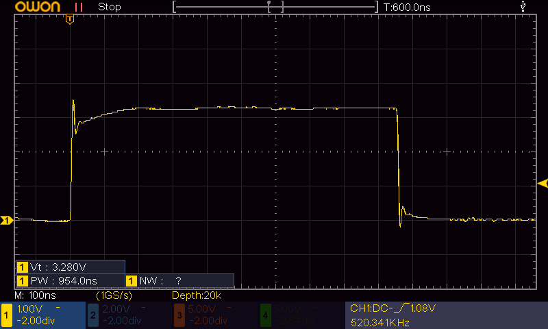
通常のArduinoと同じ関数で使用可能です。digitalWrite()のスピードは約477nsでした。
void setup() {
  pinMode(D0, OUTPUT);
}

void loop() {
  digitalWrite(D0,HIGH);
  digitalWrite(D0,LOW);
}
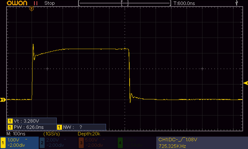
ちなみにRenesas RAマイコンのFSPを使用すると少し早くなり、約313nsになりました。
Arduinoの標準関数は抽象化されている分だけ若干遅くなるようですが、この程度の差なら普通に使う分には問題ないかと思います。
void setup() {
  R_IOPORT_PinCfg(NULL, BSP_IO_PORT_00_PIN_14, IOPORT_CFG_PORT_DIRECTION_OUTPUT);
}

void loop() {
  R_IOPORT_PinWrite(NULL, BSP_IO_PORT_00_PIN_14, BSP_IO_LEVEL_HIGH);
  R_IOPORT_PinWrite(NULL, BSP_IO_PORT_00_PIN_14, BSP_IO_LEVEL_LOW);
}
アナログ入力(ADC)
ADCはA0~A5の6ピンで使用可能です。使用方法は通常のArduinoと同じです。
レンジのデフォルト値は10bit(0~1023)で、最大で14bit(0~16383)まで上げることが出来ます。
void setup() {
  Serial.begin(115200);
  pinMode(A0, INPUT);

  analogReadResolution(14);  // ADCレンジ設定
}

void loop() {
  Serial.println(analogRead(A0));
  delay(1000);
}
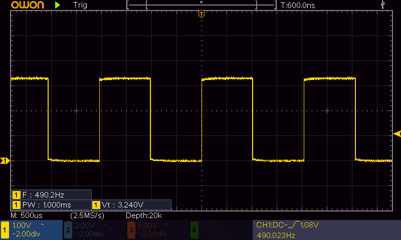
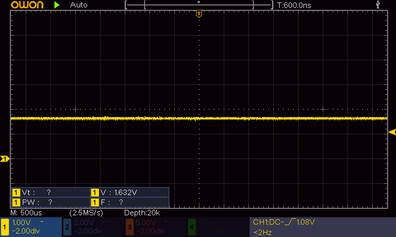
DAC出力、PWM出力
RA4M1にはDACが内蔵されており、ピンによってanalogWrite()の挙動が変わります。
| PWM出力 | D5、D6、D7、D8、D9、D10 |
| DAC出力 | D0 |
void setup() {
  pinMode(D5, OUTPUT);
  analogWrite(D5, 127);
}

void loop() {
}
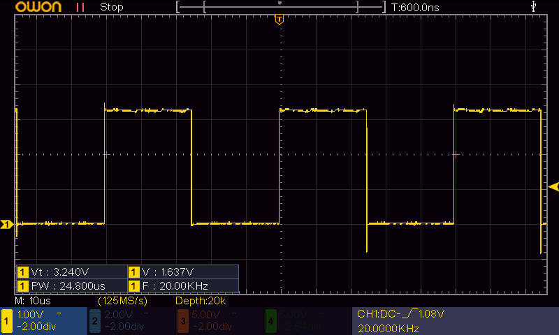
PWM周波数を変更したい場合はRA4M1の標準ライブラリである"pwm.h"を使用します。
#include "pwm.h"

const float PWM_FREQ = 20000.0;  // 周波数:20kHz

PwmOut pwm5(D5);

void setup() {
  pwm5.begin(PWM_FREQ, 0.0); // Duty:0%
}

void loop() {
  pwm5.pulse_perc(50.0);  // Duty:50%
  delay(3000);
  pwm5.pulse_perc(20.0);  // Duty:50%
  delay(3000);
}